
A practical reference for casting buyers and engineers specifying cast metal components
Published by The Casting Manufacturers Association (TCMA)
TCMAINC.com
Surface finish is one of the most frequently misspecified characteristics on casting drawings — and one of the most common sources of supplier disputes, rejected parts, and unexpected cost. Specifying a finish that's tighter than the process can reliably deliver forces machining that wasn't budgeted. Specifying one that's too loose causes functional or assembly failures downstream.
This guide gives buyers, engineers, and procurement teams a clear picture of what each casting process actually delivers in terms of surface finish and dimensional tolerance — not idealized best-case numbers, but honest, production-realistic ranges. For foundries, it's a useful reference when explaining process capabilities to new customers who may not have casting-specific experience.
How to use this guide: Find your casting process, review the typical surface finish and tolerance ranges, then compare against your part's functional requirements. If your requirements fall outside the typical range for your current process, this guide will tell you which process alternatives to consider.
Before diving into process comparisons, a brief primer on how surface finish is measured — because the terminology is frequently misused on drawings.
Ra (Roughness Average) is the most common surface finish measurement in manufacturing. It represents the average deviation of the surface profile from a mean line, measured in microinches (µin) or micrometers (µm). Lower Ra = smoother surface.
Common Ra reference points:
Rz (Average Maximum Height) and Rmax (Maximum Roughness Height) are also used, particularly in European and aerospace specifications. If your drawing calls for Rz or Rmax instead of Ra, confirm the measurement basis with your foundry — the numbers are not interchangeable.
Important: As-cast surface finish is not uniform across an entire casting. Gate locations, parting lines, core prints, and areas of turbulent fill will always be rougher than the main body surfaces. Specify surface finish by zone if you have areas with different requirements.
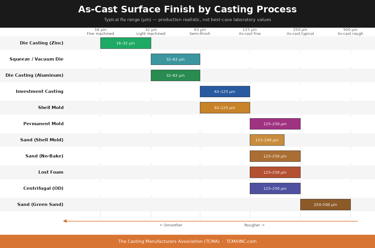
Typical as-cast surface finish: 250–500 Ra µin (green sand); 125–250 Ra µin (no-bake/air-set); 125–200 Ra µin (shell mold)
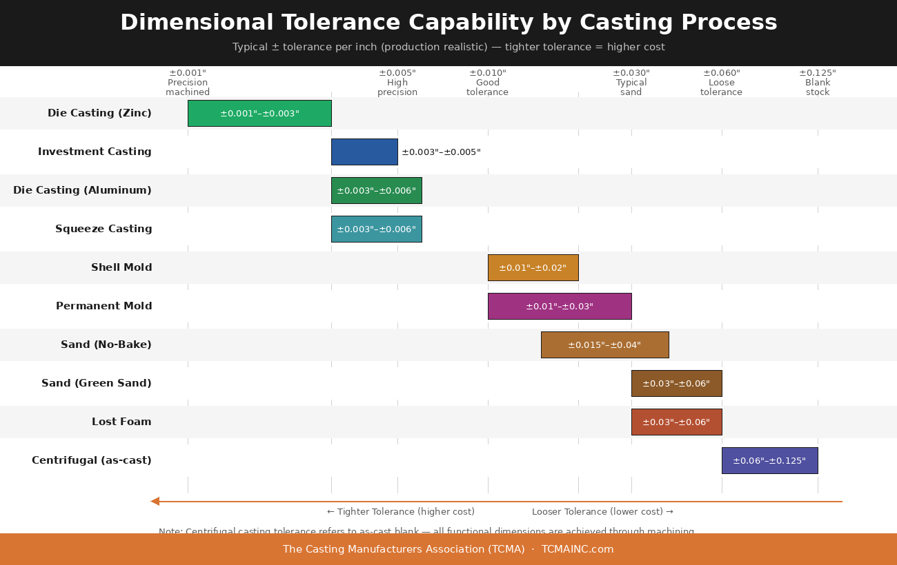
Typical dimensional tolerance: ±0.030" to ±0.060" for most features; tighter to ±0.015" with precision patterns and controlled process; looser on large castings or across parting lines
What drives finish variation in sand casting:
When machining is typically required:
Sand castings almost always require machining on sealing surfaces, bearing bores, threaded features, and any surface requiring tolerances tighter than ±0.020". Plan machining stock of 0.060"–0.125" on critical surfaces in your design.
Common defects and how they're managed:
Design tips to improve sand casting finish:
Typical as-cast surface finish: 63–125 Ra µin standard; 32–63 Ra µin achievable with fine ceramic shell and controlled dewax/firing
Typical dimensional tolerance: ±0.005" per inch for most features; ±0.003"–0.004" per inch achievable with process optimization; larger parts tolerance loosens proportionally
What drives finish variation in investment casting:
When machining is typically required:
Investment casting's primary value proposition is minimizing machining. Many surfaces can be used as-cast with no further processing. Machining is typically required only for bearing bores, precision mating surfaces, threaded features, and features requiring tolerances tighter than ±0.003" per inch. Always review the part design with the foundry to identify which surfaces are as-cast acceptable before specifying a machining scope.
Common defects and how they're managed:
Design tips to improve investment casting accuracy:
Typical as-cast surface finish: 32–63 Ra µin (aluminum); 16–32 Ra µin (zinc); 63–125 Ra µin (magnesium)
Typical dimensional tolerance: ±0.002"–0.005" per inch (zinc — tightest); ±0.003"–0.006" per inch (aluminum); parting line features may be ±0.005"–0.010" depending on die condition
What drives finish variation in die casting:
When machining is typically required:
Die casting is designed to minimize machining, and most production die castings require only spot-faced or drilled/tapped features. However, machining is required for: bearing bores requiring concentricity tighter than ±0.005", pressure-tight sealing surfaces, and features requiring tolerance tighter than ±0.002" per inch.
Porosity — the critical topic for die casting:
Die casting porosity deserves special attention because it's the process's primary structural limitation. Entrapped gas during high-speed injection creates subsurface voids that are invisible as-cast but emerge during machining or cause leak failures in pressure-tight applications.
How to address porosity in your specification:
Common defects and how they're managed:
Design tips for die casting:
Typical as-cast surface finish: 125–250 Ra µin standard; 63–125 Ra µin achievable with optimized die coating and pour technique
Typical dimensional tolerance: ±0.015"–0.030" per inch for most features; tighter to ±0.010" with process optimization; better than sand casting due to rigid metal mold
What drives finish variation in permanent mold:
When machining is typically required:
Similar to sand casting but with tighter starting tolerances. Bearing bores, sealing surfaces, and precision mating features require machining. Permanent mold castings typically need less machining stock than sand castings (0.040"–0.090" on critical surfaces) due to better dimensional stability.
Common defects and how they're managed:
Typical as-cast surface finish (OD): 125–250 Ra µin; OD surface quality depends on mold type (metal mold = finer, sand-lined = rougher)
Typical as-cast surface finish (ID/bore): 250–500 Ra µin as-cast before boring; the ID is always machined in final production
Typical dimensional tolerance: OD ±0.060"–0.125" as-cast (machined to final); ID is bored to print; wall thickness variation ±0.060"–0.125"
Important note for centrifugal castings: Centrifugal casting is almost never used as a net-shape process. The product is a near-net-shape cylinder that is machined to final dimensions — OD turned, ID bored, faces milled, features machined. Surface finish and tolerance on the drawing refer to the machined part, not the as-cast blank. Specify as-cast dimensions only for rough blank procurement; all functional dimensions should reference finished machined condition.
What makes centrifugal castings unique from a quality standpoint:
Squeeze Casting:
Vacuum Die Casting:
Lost Foam Casting:
Shell Mold Casting:
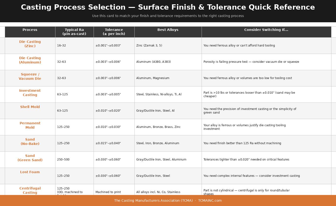
Use this decision guide when your current casting process isn't meeting your finish or tolerance requirements.
If your sand casting surface finish is too rough:
→ Switch to no-bake or shell mold (same tooling cost range, better finish)
→ Add a secondary shot blast or vibratory finishing operation (low cost, moderate improvement)
→ For significant improvement, consider investment casting if alloy and part size allow
If your sand casting tolerances are too loose:
→ Add machining on critical features (most economical path)
→ Switch to permanent mold (better tolerances, similar alloy range for non-ferrous)
→ Switch to investment casting for ferrous or complex geometries
If your die casting has porosity problems on a pressure-tight part:
→ Specify vacuum-assisted die casting (upgrade within same process family)
→ Switch to squeeze casting (highest integrity, higher cost)
→ Switch to permanent mold gravity die (lower injection pressure, lower porosity risk)
If your investment casting tolerances are drifting:
→ Review wax pattern die condition — this is usually the root cause
→ Add in-process dimensional checks at the wax stage, not just the finished casting stage
→ Consider adding CMM first article inspection to every lot until root cause is resolved
If your permanent mold casting finish is inconsistent lot to lot:
→ Audit die coating application process — inconsistency here is the most common cause
→ Check die temperature consistency with thermocouple logging
→ Review mold wash type — some alloy/coating combinations perform better than others
Before finalizing a casting drawing, review these specification practices to avoid the most common mistakes:
1. Specify finish by zone, not globally
A global surface finish callout (the standard triangle symbol with Ra value on the title block) applies to all surfaces. For castings, this is almost never appropriate — the parting line, gates, and core prints will never match the body surface finish. Use zone-specific callouts for surfaces that actually matter.
2. Distinguish "as-cast" from "machined" surfaces
Mark which surfaces are as-cast on your drawing. Foundries will quote and control as-cast surfaces differently from machined surfaces. If you don't specify, you may pay for machining on surfaces that didn't need it.
3. Don't over-specify
Tighter finish and tolerance = higher cost. Every casting has a "natural" finish range for its process — specifying inside that range costs nothing extra. Specifying outside it costs significantly more. Use this guide's ranges as your baseline before adding drawing requirements.
4. Provide a visual reference for cosmetic surfaces
Written Ra values on drawings don't convey "looks good" very well. For Class A cosmetic surfaces, provide a visual limit sample (a physical part or photograph) showing acceptable vs. unacceptable appearance. This is common practice in automotive but valuable in any application with appearance requirements.
5. Confirm finish measurement method
If your specification uses Ra, confirm your foundry and your inspection team measure Ra the same way — same cutoff length (typically 0.030" or 0.100" for castings), same traverse speed, same instrument calibration standard. Measurement disputes on finish are almost always methodology disputes, not actual non-conformances.
TCMA's directory includes verified casting foundries organized by process. Browse foundries that specialize in your required casting process, or submit your project details and let us match you with the right supplier for your alloy, finish requirements, and production volume.
Not sure which casting process will meet your surface finish and tolerance requirements?
Submit your part details at TCMAINC.com — include your alloy, functional finish requirements, and tolerance needs — and we'll help you identify the right process and the right foundry.
Visit TCMAINC.com to browse verified casting manufacturers.
Published by The Casting Manufacturers Association | TCMAINC.com | Supporting North American foundries and the buyers who rely on them